Broadband Isolator Technology Analysis: Principle, Design and Application Evolution
Broadband Isolator is a non-reciprocal RF device designed for broadband signals. It ensures the stability and security of high-frequency systems by suppressing signal reflection and energy leakage. Its core technology is to combine the magnetic field control ability of ferrite materials with broadband matching design to cover the wide frequency band requirements from microwave to millimeter wave. This article systematically analyzes the principle, design, application and future trends.
I. Technical Principles and Core Characteristics
Non-reciprocity and Faraday Rotation Effect
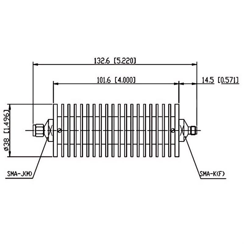
The core working principle of Broadband Isolator is based on the Faraday rotation effect of ferrite materials. When the RF signal passes through the magnetized ferrite, the polarization direction of the electromagnetic wave rotates. Combined with the microstrip line or coaxial structure, low-loss transmission in the forward direction (insertion loss <0.5dB) and high isolation in the reverse direction (isolation >30dB) are achieved. The reflected signal is guided to the isolation port and dissipated as heat energy through the matching resistor, thereby blocking reverse interference13.
Wideband matching design
Impedance matching: By adjusting the microstrip line width and substrate dielectric constant (such as ROGERS 4350B), ensure 50Ω characteristic impedance and reduce standing wave ratio (VSWR <1.2)13.
Multilayer ferrite integration: Using low-temperature co-fired ceramic (LTCC) technology, the ferrite layer is integrated with the transmission line to reduce parasitic parameters (parasitic inductance <0.5nH), support DC~40GHz broadband operation, and some models can be expanded to 110GHz34.
High power and thermal management
The combination of aluminum nitride (AlN) substrate and copper-tungsten alloy heat sink supports continuous wave power of 50W@6GHz and instantaneous pulse power tolerance of 1kW@1μs. Metallized through-holes (Via) quickly conduct heat to the ground layer to ensure reliability in high-density scenarios13.
II. Key design elements
Material selection
Ferrite material: yttrium iron garnet (YIG) or nickel zinc ferrite (Ni-Zn), hysteresis loss <0.1dB/GHz, temperature stability of ±0.01dB/℃13.
Substrate material: high-frequency low-loss substrate (such as ROGERS 4003C) for millimeter wave band (28GHz/39GHz), dielectric constant tolerance ±0.05, to ensure signal integrity35.
Structural optimization
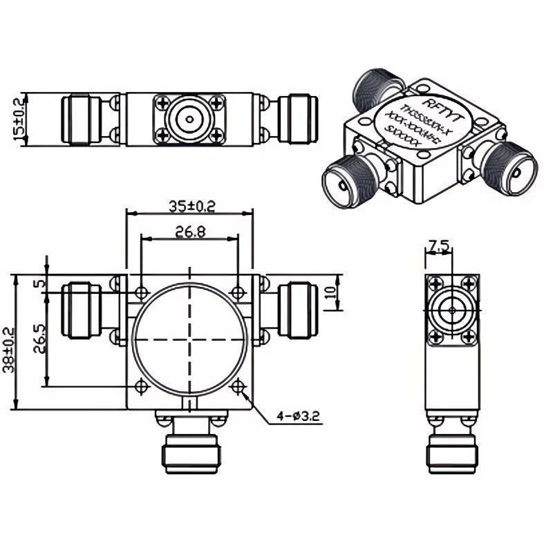
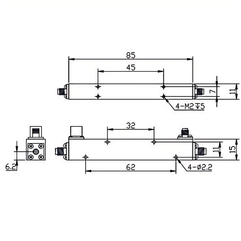
Miniaturized packaging: Surface mount (SMT) is compatible with standard PCB process, with a size as low as 10mm×10mm×2mm, suitable for 5G Massive MIMO antenna arrays and vehicle-mounted radar modules36.
Dynamic magnetic field tuning: The bias magnetic field is adjusted in real time through the electromagnetic coil to achieve adaptive frequency band switching (±15%), and flexibly respond to multi-band communication needs34.
Performance parameter verification
Vector network analyzer (VNA) test: measure S parameters (S21/S12), isolation and return loss to ensure performance consistency within the frequency band13.
Extreme environment test: pass MIL-STD-810H vibration test and -55℃~+125℃ temperature cycle verification, meet aerospace and automotive radar standards36.
III. Typical application scenarios
5G and satellite communications
Massive MIMO base station: in the 64T64R antenna array, the isolator protects the power amplifier (PA) from antenna mismatch reflection, reducing the failure rate by 70%13.
Low-orbit satellite terminal: suppress signal reflection of LEO satellite link, improve uplink efficiency, and adapt to SpaceX Starlink and other systems36.
Radar and electronic countermeasures
77GHz automotive radar: isolate the crosstalk between the transmit chain and the receive chain, improve the angular resolution by 20%, and adapt to Tesla and BYD intelligent driving platforms36.
Phased array radar T/R module: prevent high-power pulses from damaging low-noise amplifiers (LNAs) and support multi-channel synchronization of electronic warfare systems13.
Test instruments and medical equipment
Vector network analyzer calibration: absorb 10kV high-voltage pulses to ensure measurement safety36.
Radiofrequency therapy device: transmit energy to the treatment head in a directional manner to avoid reverse radiation damage to the generator15.
IV. Technical challenges and future trends
Current technical bottlenecks
Millimeter wave loss: >30GHz ferrite eddy current loss increases significantly, and low-dimensional magnetic materials (such as two-dimensional ferromagnets or hexagonal ferrites doped with rare earth elements) need to be developed36.
Temperature sensitivity: performance fluctuates under extreme temperatures, and the temperature coefficient of materials needs to be optimized (such as graphene composite materials)35.
Innovation direction
Intelligent reconfigurable design: integrate MEMS or liquid crystal materials to achieve dynamic switching of frequency bands (such as software-defined radio), and the isolation is increased to 40dB@40GHz34.
Photonic-RF hybrid isolation: heterogeneous integration of silicon photonic chips and ferrites, supporting the coordinated processing of optical-RF signals and reducing transmission losses45.
Green manufacturing: using recyclable magnetic materials and lead-free processes, carbon emissions are reduced by 50%, in line with the EU RoHS 3.0 standard36.
V. Summary
Broadband Isolator has become a core component of 5G/6G, satellite communications and radar systems due to its broadband coverage, high isolation and compact design. In the future, with the breakthrough of new materials (such as topological insulators) and intelligent tuning technology, it will evolve towards higher frequency bands (THz) and lower losses, providing key support for the integrated network and full coverage of air, land, and sea.
Publisher: RF Solution http://solutionrf.com/ http://solutionrf.com/logo.png 236 48 ...Please wait.